
Innovation
Performance and versatility through the latest technology.

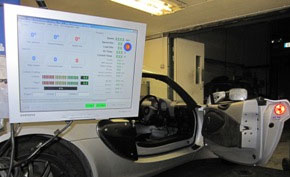
Calibration
Optimal performance through precise calibration.

Performance
Robust design and extensive development ensures reliability.

Welcome to Emerald!
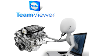
We are the creators and manufacturers of aftermarket standalone K6 ECU (Engine Control Unit) or EMS (Engine Management System) with over 27 years of experience in automotive electronics, engine management and calibration as a company. Founder of Emerald M3D Ltd is Dave Walker, well known in the UK for his many articles and features in various motorsport publications and huge experience in engine management, Dave has now celebrated 60 years in the automotive industry. He is currently Technical Editor at Practical Performance Car magazine and a regular contributor to Track Driver Magazine. Some of his knowledge can be found on this website in "Knowledge Zone", "Projects" and "Walker's Workshop" blogs under Articles tab.
Our aim is to provide user-friendly, capable and reliable engine management systems with 1st-class back-up and technical assistance – whilst at the same time not costing the earth. Emerald engine management systems are capable of handling full 3D mapping of both ignition and injection on most normally aspirated and turbo engines – from classics through to the latest engine designs. Emerald systems are both straight-forward and logical to use and many of the "big" features found in competitor systems are included as standard in Emerald’s ECU’s. Work is always ongoing to add more features and functionality to cater for the ever-growing diversity of engines and customer requirements. Future developments will include adding new features to the K6 ECU as well as expanding the product range and further enhancement of on-site and over-seas facilities and support in addition to our already extensive base of dealers in different parts of the world.